Visualizzazione post con etichetta arduino. Mostra tutti i post
Visualizzazione post con etichetta arduino. Mostra tutti i post
venerdì 26 marzo 2021
sabato 24 dicembre 2016
Simple Arduino Breathalyzer
Simple Arduino Breathalyzer

Introduction
The MQ series of gas sensors use a small heater inside with an electro-chemical sensor.
They can be calibrated more or less but a know concentration of the measured gas or gasses is needed for that.
They are sensitive for a range of gasses and are used indoors at room temperature.
The output is an analog signal and can be read with an analog input of the Arduino.
They can be calibrated more or less but a know concentration of the measured gas or gasses is needed for that.
They are sensitive for a range of gasses and are used indoors at room temperature.
The output is an analog signal and can be read with an analog input of the Arduino.
SainSmart MQ-3
The analog gas sensor - MQ3 is used in gas leakage detecting equipments in consumer and industry markets, this sensor is suitable for detecting LPG, i-butane, propane, methane ,alcohol, Hydrogen, smoke.
It has a high sensitivity and fast response time.And the sensitivity can be adjusted by the potentiometer.
The MQ-3 is an alcohol gas sensor that is available for about $5.
Connetting
Sensor-Arduino
GND - GND
A0 - A0
VCC - 5V
Arduino Schetch
Test Code:
int val=0;
void setup(){
Serial.begin(9600);
}
void loop(){
val=analogRead(A0);
Serial.println(val);
delay(100);
}
Link App
https://drive.google.com/file/d/1naIS3WD_Boty_EjX_9em6Vw1NMy59dps/view?usp=sharing

mercoledì 15 giugno 2016
Arduino Tutorial - Easy secret knock detector
In this project I build a circuit with a Led and a piezo to function as a
on and off a Led when it receives a number of knocking sounds within a
given range.

Hardware

Step 1: Things you need
- LED
- Diode(Zener 5.1v).
- Piezo Buzzer
- 470Ω Resistor
- 1MΩ Resistor
- Arduino uno
- jumper wire
- Breadboard
- Arduino IDE
Step 2: Watch the video tutorial
Step 3: Schematics

The circuit is so simple:
Arduino Pins: Breadboard:
Pin A2 --------------------------1MΩ-------------------Gnd
Pin A2 ------------------------Diode-------------------Gnd
Pin A2 ------------------Piezo Buzzer---------------Gnd
Pin 8 -------------------------470Ω-------Led 1------Gnd
Gnd-------------------------------------------------------Gnd
Arduino Pins: Breadboard:
Pin A2 --------------------------1MΩ-------------------Gnd
Pin A2 ------------------------Diode-------------------Gnd
Pin A2 ------------------Piezo Buzzer---------------Gnd
Pin 8 -------------------------470Ω-------Led 1------Gnd
Gnd-------------------------------------------------------Gnd
Step 4: Arduino Sketch
"const int outputPin = 5; // led indicator connected to digital pin
const int knockSensor = A2; // the piezo is connected to an analog pin
const int thresholdHIGH =120; // threshold value to decide when the
detected knock is hard (HIGH) const int thresholdLOW = 70; // threshold
value to decide when the detected knock is gentle (LOW) const int
secretKnockLength = 3; //How many knocks are in your secret knock /*
This is the secret knock sequence * 0 represents a LOW or quiet knock *
1 represents a HIGH or loud knock * The sequence can be as long as you
like, but longer codes increase the difficulty of matching */ const int
secretKnock[secretKnockLength] = {0, 0, 1}; int secretCounter = 0;
//this tracks the correct knocks and allows you to move through the
sequence int sensorReading = 0; // variable to store the value read from
the sensor pin void setup() { //Set the output pin as an OUTPUT
pinMode(outputPin, OUTPUT); //Begin Serial Communication.
Serial.begin(9600); } void loop() { // read the piezo sensor and
store the value in the variable sensorReading: sensorReading =
analogRead(knockSensor); // First determine is knock if Hard (HIGH)
or Gentle (LOW) //Hard knock (HIGH) is detected if (sensorReading
>= thresholdHIGH) { //Check to see if a Hard Knock matches the
Secret Knock in the correct sequence. if (secretKnock[secretCounter]
== 1) { //The Knock was correct, iterate the counter.
secretCounter++; Serial.println("Correct"); } else {
//The Knock was incorrect, reset the counter secretCounter
= 0; Serial.println("Fail"); digitalWrite(outputPin, LOW);
}//close if //Allow some time to pass before sampling again to
ensure a clear signal. delay(100); //Gentle knock (LOW) is
detected } else if (sensorReading >= thresholdLOW) { //Check
to see if a Gentle Knock matches the Secret Knock in the correct
sequence. if (secretKnock[secretCounter] == 0) { //The Knock
was correct, iterate the counter. secretCounter++;
Serial.println("Correct"); } else { //The Knock was
incorrect, reset the counter. secretCounter = 0;
Serial.println("Fail"); }//close if //Allow some time to
pass before sampling again to ensure a clear signal. delay(100);
}//close if else //Check for successful entry of the code, by
seeing if the entire array has been walked through. if (secretCounter
== (secretKnockLength) ) { Serial.println("Welcome"); //if
the sececret knock is correct, illuminate the LED for a couple seconds
digitalWrite(outputPin, HIGH); //Reset the secret counter
to 0. secretCounter = 0; }//close success check }//close
loop".
martedì 23 giugno 2015
Arduino Tutorial How to control Arduino with Bluetooth
Arduino Tutorial
In this tutorial I'll show you How to control Arduino with Bluetooth
using, My app developed with app inventor.
Parts Required
- 1x Arduino
- 1x Bluetooth Module ( HC-06)
- 1x Smartphone (any Android will work)
- 1x Led
- 3x resistors
- 1x Breadboard
- Jumper Cables
Schematics

Arduino Sketch
int ledblue=2;
int tx=1;
int rx=0;
char inSerial[15];
void setup(){
Serial.begin(9600);
pinMode(ledblue, OUTPUT);
pinMode(tx, OUTPUT);
pinMode(rx, INPUT);
allpinslow();
}
void loop(){
int i=0;
int m=0;
delay(500);
if (Serial.available() > 0) {
while (Serial.available() >
0) {
inSerial[i]=Serial.read();
i++;
}
inSerial[i]='\0';
Check_Protocol(inSerial);
}}
void allpinslow()
{
digitalWrite(ledblue, HIGH);
digitalWrite(ledblue, LOW);
}
void Check_Protocol(char inStr[]){
int i=0;
int m=0;
Serial.println(inStr);
if(!strcmp(inStr,"2off")){
//Led Off
allpinslow();
digitalWrite(ledblue, LOW);
Serial.println("Blue Off");
for(m=0;m<11;m++){
inStr[m]=0;}
i=0;}
if(!strcmp(inStr,"2on")){
//Led on
allpinslow();
digitalWrite(ledblue, HIGH);
Serial.println("Blue on");
for(m=0;m<11;m++){
inStr[m]=0;}
i=0;}
else{
for(m=0;m<11;m++){
inStr[m]=0;
}
i=0;
}}
Notes and Tips:
- You need to remove the RX and TX cables when you’re uploading the sketch to your Arduino.
- If the HC-05 Bluetooth Module asks for a password, It’s’1234′.
- Sometimes people connect the TX from the bluetooth module to the TX of the Arduino… that’s wrong and it won’t work. Make sure you connect it properly, the TX into RX and the RX into the TX.
martedì 14 ottobre 2014
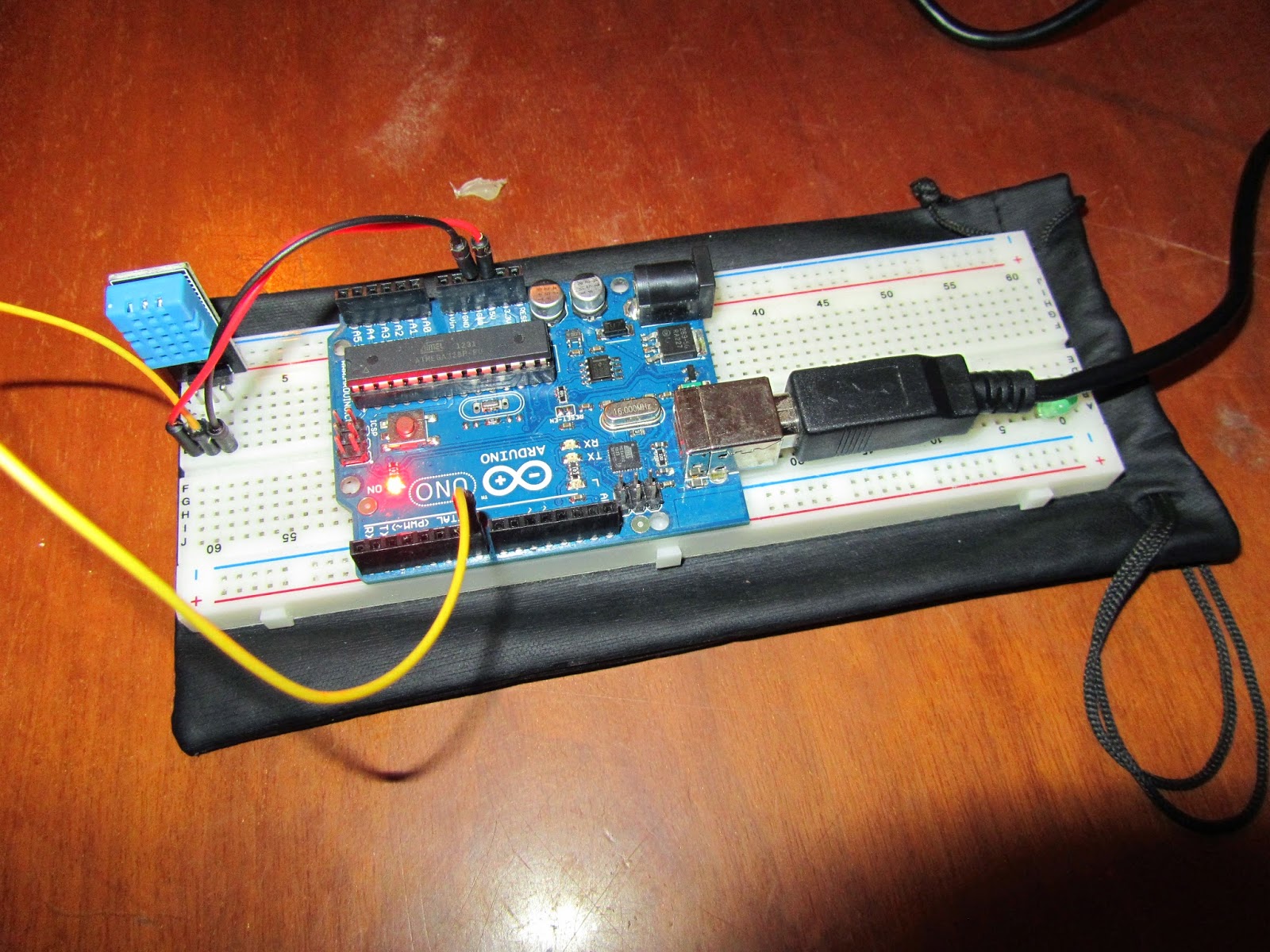
Dht11 Temperature and Humidity Sensor
The DHT11 is a basic, low-cost digital temperature and humidity sensor.
Its fairly simple to use, but requires careful timing to grab data.
Technical Details
Low Cost
3 to 5V power and I/O
2.5mA max current
Good for 20-80% humidity readings with 5% accuracy
Good for 0-50°C temperature readings ±2°C accuracy
No more than 1 Hz sampling rate (once every second)
Body size 15.5mm x 12mm x 5.5mm
Test sketch
//
// FILE: dht11_test1.pde
// PURPOSE: DHT11 library test sketch for Arduino
//
#include <dht11.h>
dht11 DHT;
#define DHT11_PIN 7
void setup(){
Serial.begin(9600);
Serial.println("DHT TEST PROGRAM ");
Serial.print("LIBRARY VERSION: ");
Serial.println(DHT11LIB_VERSION);
Serial.println();
Serial.println("Type,\tstatus,\tHumidity (%),\tTemperature (C)");
}
void loop(){
int chk;
Serial.print("DHT11, \t");
chk = DHT.read(DHT11_PIN); // READ DATA
switch (chk){
case DHTLIB_OK:
Serial.print("OK,\t");
break;
case DHTLIB_ERROR_CHECKSUM:
Serial.print("Checksum error,\t");
break;
case DHTLIB_ERROR_TIMEOUT:
Serial.print("Time out error,\t");
break;
default:
Serial.print("Unknown error,\t");
break;
}
// DISPLAT DATA
Serial.print(DHT.humidity,1);
Serial.print(",\t");
Serial.println(DHT.temperature,1);
delay(1000);
}
A tutorial on how to connect a DHT11 Sensor to your Arduino
Its fairly simple to use, but requires careful timing to grab data.
Technical Details
Low Cost
3 to 5V power and I/O
2.5mA max current
Good for 20-80% humidity readings with 5% accuracy
Good for 0-50°C temperature readings ±2°C accuracy
No more than 1 Hz sampling rate (once every second)
Body size 15.5mm x 12mm x 5.5mm
Test sketch
//
// FILE: dht11_test1.pde
// PURPOSE: DHT11 library test sketch for Arduino
//
#include <dht11.h>
dht11 DHT;
#define DHT11_PIN 7
void setup(){
Serial.begin(9600);
Serial.println("DHT TEST PROGRAM ");
Serial.print("LIBRARY VERSION: ");
Serial.println(DHT11LIB_VERSION);
Serial.println();
Serial.println("Type,\tstatus,\tHumidity (%),\tTemperature (C)");
}
void loop(){
int chk;
Serial.print("DHT11, \t");
chk = DHT.read(DHT11_PIN); // READ DATA
switch (chk){
case DHTLIB_OK:
Serial.print("OK,\t");
break;
case DHTLIB_ERROR_CHECKSUM:
Serial.print("Checksum error,\t");
break;
case DHTLIB_ERROR_TIMEOUT:
Serial.print("Time out error,\t");
break;
default:
Serial.print("Unknown error,\t");
break;
}
// DISPLAT DATA
Serial.print(DHT.humidity,1);
Serial.print(",\t");
Serial.println(DHT.temperature,1);
delay(1000);
}
A tutorial on how to connect a DHT11 Sensor to your Arduino
Iscriviti a:
Post (Atom)
-
Arduino Tutorial In this tutorial I'll show you How to control Arduino with Bluetooth using, My app developed with app inventor. ...
-
 In this video, I'll given a simple demo of the alarm I built using Arduino UNO interfaced with DHT11 Temperature sensor and a Buzzer.
 -
Ecco il link per il materiale delle lezioni : https://t.me/CorsoIOTDaVinci